Last Updated on July 3, 2022
In heat pumps and refrigerators one of the major four processes is compression. It involves the application of pressure on the working fluid to decrease its volume and add to its internal energy.
It is the only process in which work is done on the refrigerant in the entire cycle. It has two basic types: wet compression and dry compression. This article specifically covers the difference between wet and dry compression in detail.
Whether compression is wet or dry depends on the state of working fluid during compression. If refrigerant or fluid inside compressor is completely gaseous during compression, then it is called dry compression. If refrigerant or fluid is partially liquid, even minutely, during compression, then it is called wet compression.
This means that during dry compression liquid will be in saturated vapor state or superheated state.
Saturated vapor state is the one in which the refrigerant is in vapor state entirely and it does not have any liquid.
Superheated state of the refrigerant is the one in which entirely vapor state fluid is heated above the saturation temperature.
The explanation will clarify important concepts or refresh them so that it is easy to understand the difference between dry and wet compression in refrigerators and heat pumps.
What is Vapor Compression Cycle?
Vapor Compression Cycle allows the extraction of heat from low temperature zone and transfers it to high temperature zone. It is the most common cycle used in refrigerators.
VCC consists of 4 basic processes
- Compression
- Condensation
- Throttling
- Evaporation.
A brief working of the processes included in vapor compression cycle are provided below:
Compression
Initially the refrigerant is compressed adiabatically in the compressor. This allows the low temperature and low pressure refrigerant to be converted to high pressure and high temperature refrigerant.
The volume decrease with the increase in pressure. This indicates increment in the internal energy due to decrease in the spacing in between refrigerant molecules.
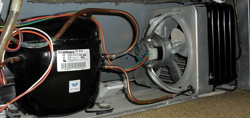
Electrically operated reciprocating compressor are used for compression usually. However compressors are of several types including centrifugal, screw, scroll etc.
Condensation
After compression high pressure and high temperature fluid is allowed to move into the condenser. Condenser plays the role of removal of heat from the refrigerant at high pressure.
The heat removed from the refrigerant theoretically neither affects pressure nor temperature. Thereby this process is isobaric (constant pressure) as well as isothermal (constant temperature).
The enormous amount of heat removed from the refrigerant in the condenser is called heat of condensation.
There are two major types of condensers:
Air-cooled
Air-cooled condenser are used for small refrigeration and air-conditioning units. It is favorable in a way that it is convenient when it comes to maintenance as scaling is not a problem.
Initial cost is low and it is free from excess piping required in water-cooled condensers.
The removal of heat is mainly through natural convection or forced convection.
In most of air conditioners air is allowed to pass through the external surface area of fins within which refrigerant travels.
Water-Cooled
They are particularly used for large air-conditioning systems. The most common sub-type is shell and tube.
Overall power consumption per tonnage of water-cooled conditioning system is lower as compared to that of air-cooled conditioning system.
The downside though is that maintenance cost is about 3 to 4 times to that of air-cooled conditioning systems. Maintenance mainly includes getting rid of scaling and algae in piping through acid compound.
Throttling and Expansion
Throttling or expansion process allows decrease in pressure and temperature of the refrigeration after passing from throttling valve.
The valve actually allows sudden increase in the cross-sectional area that expands the refrigerant decreasing its pressure. There refrigerant is almost 75% liquid after this stage.
Despite cooling of the refrigerant through expansion throttling actually controls the amount of liquid sent to evaporator.
Throttling valve can actually be a plug with holes or even a thin slit.
Evaporation
Evaporator is the output section of the refrigerator or air-conditioning system. It is the component that accounts for the refrigeration effect induced by the cooling system.
Evaporator allows the absorption of heat through the surrounding as the refrigerant moves through the refrigerant coils. The process is called evaporation.
Theoretically evaporation is isothermal as there is no change in the temperature of refrigerator as the refrigerant boils during its movement through the evaporation coils.
The heat absorbed by the application of evaporation is thereby called latent heat of vaporization (latent heat required to convert liquid refrigerant to vapor). It is the same as heat of condensation as the energy required to convert liquid refrigerant to vapor and vice versa is the same.
Normally there are two types of evaporators: Air-cooling and Water-cooling.
The simple difference between these two types is the type of fluid they absorb energy from. In air-cooling evaporator heat is absorbed from the air i.e. from the surroundings as in normal air-conditioning units. While in water-cooling evaporator heat is absorbed from the water that is in direct contact with the evaporator coils.
Difference b/w Wet and Dry Compression
After it is clear that wet compression takes place when the refrigerant is in liquid-vapor state during compression the concept is illustrated in Pressure-Enthalpy (P-h) and Temperature-Entropy (T-s) diagram.
Wet Compression Diagram with Explanation
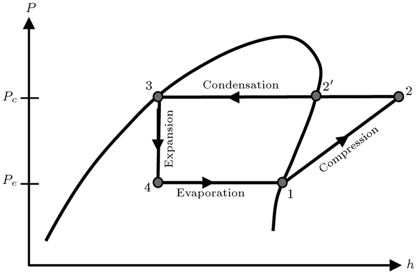
The theoretical graphs provided below represent the wet compression cycle.
The processes presented by the cycle are clearly labelled in the diagram. The red lines on either side represent the saturation curve.
Saturation curve is the line at which the fluid inside is entirely in liquid state or vapor state.
The compression in the cycle under consideration is within the saturation curve. This means that compression involves mixed phase i.e. liquid and vapor.
Thereby during compression some of the fluid will be in liquid state.
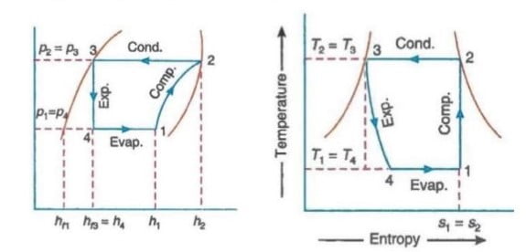
Dry Compression Diagram with Explaination
The processes presented by the cycle are clearly labelled in the diagram. The red lines on either side represent the saturation curve.
Saturation curve is the line at which the fluid inside is entirely in liquid state or vapor state.
The compression in the cycle under consideration is out of the saturation curve. This means that the fluid during the compression is either entirely in one state i.e. gaseous state.
The compression line is initiated and extended beyond the segment of saturation curve.
This segment of saturation curve represents saturated vapor state along it, so the fluid during compression will be in saturated vapor state or superheated state.
This ensures that the fluid during dry compression theoretically will be entirely in vapor state.
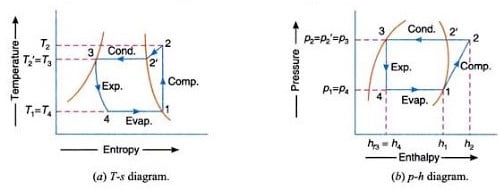
Superheat Horn
In dry compression cycle the compression begins in the saturated vapor state or superheated state. This means that the initial point of the saturation will be either on the saturation curve or after it.
The isentropic compression represented from 1-2 in the Temperature-Entropy and Pressure-Enthalpy diagram respectively usually extends beyond the condenser temperature (T3) in the condensation process from 2’-3.
This results in formation of sharp curve in the T-s diagram of dry compression cycle represented from 2-2’.
This area covered by sharp curve is otherwise named as superheat horn. On the T-s diagram it represents additional work required for dry compression.

Why Wet Compression is Not Desirable?
Wet compression is not favorable or desirable because of the damaging effect to the compressor. It can lead to deterioration of the performance of compressor in refrigerators and heat pumps and eventually making it unusable.
Some of the specific damaging effects on the compressor due to wet compression cycle are discussed below:
Entrapment of Liquid Refrigerant in the Head of Cylinder
Refrigerant in vapor state can be compressed but if the same refrigerant is in the liquid state it is uncompressible.
The refrigerant in the wet compression cycle is partially in liquid state during the compression in the compressor.
The liquid refrigerant due to its inability to be compressed results in building up elevated pressure in the head of cylinder when the piston is moving to the top dead center.
The high pressure damages the valves at head of the cylinder. This highly reduces the durability and life of the compressor rendering it ineffective in a very short duration of time.
There is an internal heat transfer process that vaporizes the liquid droplets. However it requires finite amount of time to make the entire mixture convert to vapors.
The compressor operates at very high speeds. If a compressor is running at 100 rev/s then compression would take place in 1/200 of a second which pretty fast to transfer energy to liquid droplets in the mixture inside the cylinder to convert them entirely into vapors.
Wash-up of Lubrication Oil from Walls of Cylinder
Another problem with wet compression cycle is the washing of the lubrication oil of the cylinder.
The liquid state refrigerant in wet compression cycle is in the state of droplets. This droplets during the compression go through immense pressure.
Due to inability to compress the liquid droplet tend to move in between the surfaces of piston and walls of the cylinder.
This slipping of the liquid refrigerant washes up the mandatory lubrication required and results in wear and friction ruining the performance of compressor and weakening its components.